Written with Claude.
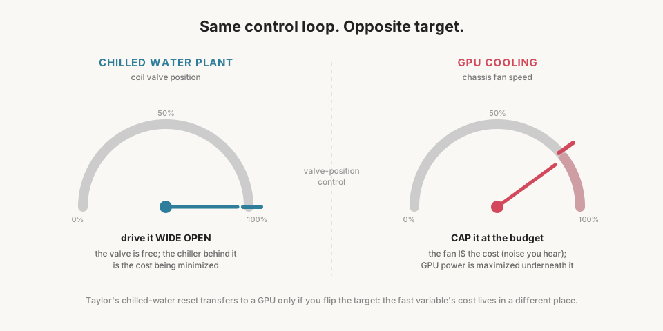
Same control loop, opposite target: I ended up running the exact sequence a chilled-water plant uses to reset its supply temperature, on a GPU, to hold a fan at a noise budget instead of driving a valve wide open.
A used 3090 lands in the living room
A used RTX 3090, rated for 350W, went into the 3900X workstation. The motivation was simple: local LLM work, training LoRA adapters (small fine-tuning add-ons layered onto a base model), running batch inference evals, the kind of thing that wants a GPU running flat out for hours at a time. The problem was where the box lives. It lives in the living room, three feet from where people sit and talk, and a card pulling 350W under load doesn’t cool itself quietly. I wanted to use as much of the silicon I’d bought as I could, without turning the room into a wind tunnel every time a training run kicked off.
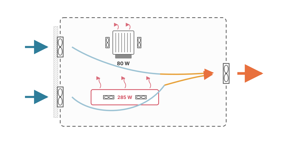
The airflow path: two 120mm intakes in front pulling through a fine mesh filter, one 120mm exhaust in the rear, and a be quiet! tower cooler rated for 250W on the CPU with its own two 120s. The 3090 is an open-fan card rather than a blower, so its cooler dumps the card’s heat straight into the case air instead of ducting it out the back. Every watt the GPU burns becomes the chassis fans’ problem, and the chassis fans are the ones a person in the room hears.
Everything is coupled, from watts to decibels
Electrical power goes into the GPU; compute happens; essentially all of that power comes back out as heat, because a chip doesn’t store energy, it burns it. Heat has to go somewhere, which means airflow, which means fan speed, which means noise. Four variables, one chain, no way to touch the first without eventually touching the last.
The fan affinity laws describe how badly that chain scales. Airflow through a fan scales linearly with its speed. Static pressure scales with speed squared. Fan power draw scales with speed cubed. Noise follows its own empirical curve, roughly 15 dB louder per doubling of speed. The asymmetry between those exponents is the entire economics of fan speed. Going from 80% to 100% buys 25% more airflow but costs nearly double the fan power (1.25 cubed is 1.95) and roughly 5 dB. The last stretch of fan speed is the most expensive cooling in the whole range, linear benefit bought at cubic cost.
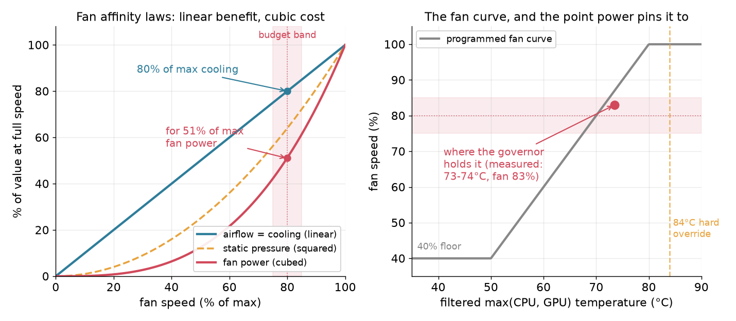 Where the budget band sits on the affinity curves, and where the governor pins the fan curve inside it.
The other half of the physics is the energy balance, the first law of thermodynamics in its air-side working form:
Q = 1.1 × CFM × ΔT
ΔT is the air’s rise through the case in °F, anchored to ambient. Ambient belongs to the room: a warm afternoon, a case panel left off. At fixed airflow and heat load, the case air sits the same ΔT above ambient, so a warmer room carries component temperatures up with it. Something in the loop has to absorb that drift, and there are only two candidates: fan speed, which a person in the room hears, or GPU power, which they don’t. We chose power. The fan holds steady and high at its budget until the power floor or the temperature override binds, because fan speed and its variation are the perceived output; power for computation is what floats to close the balance.
The same equation sizes the problem on a napkin. The GPU at its 285W cap plus roughly 80W of CPU package power feeding it (the 3900X tops at 142W; feeding a GPU takes far less) totals about 365W. Convert the watts to British units once, then stay there:
Q = 365 W × 3.412 = 1,245 BTU/hr
Allow an 18°F rise and solve for airflow:
CFM = Q / (1.1 × ΔT) = 1,245 / (1.1 × 18) ≈ 63 CFM
One 120mm fan moves that at full speed in free air. Then an IR thermometer checked it, GPU parked at its 225W floor: intake mesh 66.5°F, rear exhaust 100°F, a 34°F rise. Run the equation backward at 305W total: about 28 CFM of actual through-flow. It’s thirty-something, not a lab number (an IR gun reads grille surfaces, and the power supply vents separately), but the fine mesh and case impedance clearly cut free-air ratings to a fraction. The balance still closes: hotter air, less of it. The entire thermal problem of a 350W-class GPU is one bathroom exhaust fan of air; the hard part was only ever the noise of moving it quickly.
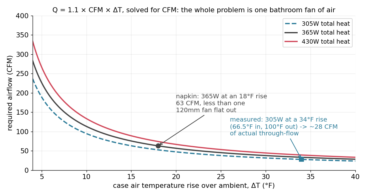 Required CFM against the case ΔT for 305W, 365W, and 430W. The measured point sits on the 305W curve.
Steadiness is the real constraint
The objective was already decided by an earlier project on this same card: it’s power-capped to 285W out of a possible 350W, a chosen efficiency point, a measured 90% of stock performance for roughly 65W less heat and noise. Given that headroom, the goal here was to extract as much of the remaining silicon as the noise budget would allow.
“Quiet” isn’t quite the right word for what a living room needs. Human hearing tracks change: a steady tone fades into the background the way a refrigerator compressor does. A fan that hunts between 60% and 90% every few seconds does not fade into anything; it draws attention every time it shifts, a dripping faucet next to a running one. That splits the constraint in two: a ceiling on fan speed, and stability at that ceiling. Solve only the ceiling and you’ve built something that still announces itself every time the workload changes.
Two inputs pulling the same variable in opposite directions
Two inputs, one controlled variable, opposite signs: raise GPU power and temperature climbs; raise fan speed and temperature falls. I wanted one pushed as high as it could go and the other pinned as low as possible. That’s a resource-allocation problem wearing a thermostat’s clothes, a shape I knew from a different domain entirely.
Chilled-water plants solve this same shape every day, and Steve Taylor wrote the sequence down plainly in Optimizing Design & Control of Chilled Water Plants, Part 5 (ASHRAE Journal, June 2012): “the CHWST setpoint is reset upwards until the valve controlling the coil that requires the coldest water is wide open.” A cooling valve at each coil is the fast, cheap variable; the chilled water supply temperature (or the pump differential pressure) is the slow, expensive one. The sequence resets the slow variable continuously until the busiest valve is pinned wide open, so the plant burns exactly as little chiller and pump energy as the worst-case zone will tolerate. Taylor names the catch: “valve position can be used to reset either CHWST setpoint or DP setpoint, but not both independently… we must decide which of the two setpoints to favor.”
Copy that sequence onto the GPU literally and it breaks immediately. The fan is the valve here, the fast variable that responds to temperature. But the fan is no free proxy; its noise is the cost I’m trying to minimize. Driving it wide open is the worst outcome available. So the target flips from “wide open” to “capped at a budget”: reset the slow variable, GPU power, to hold the fan at 80% instead of at 100%. Same architecture, same reset-the-slow-to-hold-the-fast structure, inverted target, because the objective itself is inverted: Taylor is minimizing a source behind a free valve, and I’m maximizing a source in front of a valve that costs something to open.
Building the two-loop cascade
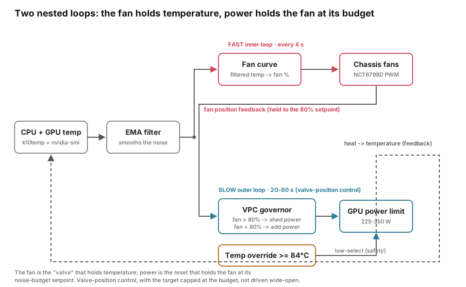
We built this as two loops running at different rates, Taylor’s separation between fast valve and slow reset. The inner loop reads CPU and GPU temperature, drives a fan curve, and adjusts PWM every few seconds. The outer loop reads fan position and trims the GPU power limit, but only every 20 to 60 seconds, so the fast loop settles before the slow one reacts.
The first version hunted. A naive fan curve keyed to max(CPU Tctl, GPU temp) chased raw temperature every 4 seconds while GPU utilization slammed between 0% and 92% per workload chunk, and the fan surged audibly right along with it.
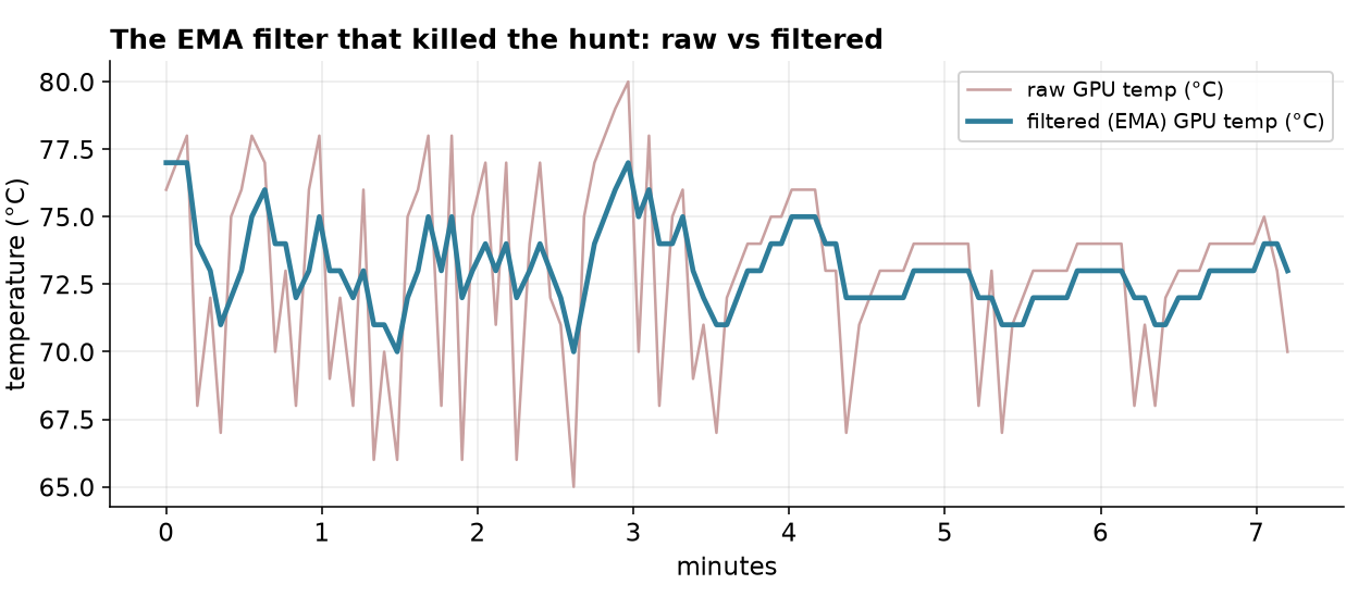
The fix came from the same HVAC playbook Taylor’s sibling articles describe for chiller short-cycling and boiler staging: widen the deadband, slow the response rate, stage off the setpoint rather than the noisy instantaneous reading. Claude wrote the filtering:
# ---- anti-hunt filtering (the fix for fan-speed hunting) ----
EMA_A=3               # EMA weight on the new sample, /10 (0.3). Lower = smoother/slower.
FAN_DEADBAND=8        # ignore fan target changes smaller than this many PWM counts (~3%)
FAN_SLEW=12           # max PWM change per cycle (~5%/4s), ramps instead of slamming
An integer EMA (filt = (filt*(10-A) + raw*A + 5) / 10) filters CPU and GPU temperature before the fan curve or the governor reads them, so both loops chase one stable number instead of raw noise. Measured over the plotted window: raw GPU temperature jumps as large as 12°C between 4-second samples smooth to at most 3°C on the filtered signal, and the fan steps instead of surging.
Filtering alone controlled the hunt, but the fan was still a byproduct of a temperature target, not something being held at a chosen value. Claude built the reframe as an explicit valve-position governor:
# --- valve-position governor: hold the FAN at FAN_SP by trimming power ---
# Priority (low-select): (1) hard temp override sheds regardless of noise budget;
# (2) fan over budget AND GPU is the heat driver (fgt>=fct, else cutting GPU power
# can't quiet a CPU-driven fan) -> shed; (3) fan under budget -> trim power up.
if   [ "$fgt" -ge "$TEMP_OVERRIDE" ]; then
  reason="OVERRIDE gpu=${fgt}°C"; hot_streak=$DOWN_CYCLES; cool_streak=0
elif [ "$fan_pct" -gt $(( FAN_SP + FAN_SP_DB )) ] && [ "$fgt" -ge "$fct" ]; then
  reason="fan ${fan_pct}% > ${FAN_SP}% budget"; hot_streak=$((hot_streak+1)); cool_streak=0
elif [ "$fan_pct" -lt $(( FAN_SP - FAN_SP_DB )) ]; then
  reason="fan ${fan_pct}% < budget, headroom"; cool_streak=$((cool_streak+1)); hot_streak=0
else hot_streak=0; cool_streak=0; fi
FAN_SP=80 is the noise budget, held within a FAN_SP_DB=5 deadband (a 75-85% hold zone), TEMP_OVERRIDE=84 is a hard shed trigger regardless of noise budget, PL_MIN=225 and PL_MAX=350 bound the power limit, and the governor steps by PL_STEP=15 on a slow 15-cycle up-trim versus a faster 5-cycle down-trim, so it sheds power quickly when hot and only climbs back cautiously. The fgt>=fct gate on the shed branch stops the governor from throttling the GPU to quiet a fan that a hot CPU is driving, knowing which constraint is binding before acting.
A crash mid-adjustment could leave the fans parked low and the card uncapped at the same time, so on any exit or signal the service restores BIOS fan auto control (pwmN_enable=5 on every channel) and drops the card back to PL_SAFE=285, well under the 350W ceiling. Verified: systemctl stop returns every channel to enable=5 and the power limit to 285.
What the trends show
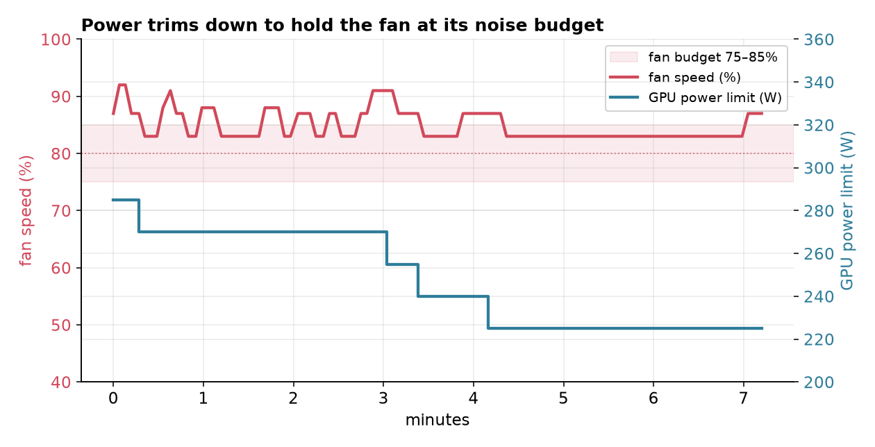
The convergence trace shows the governor stepping 15W at a time. Raising the budget to 95% to force the opposite direction, I watched power climb 285, 300, 315, 330, 345W as the fan rose from 81% to 90% chasing the higher target, logged as VPC up: fan 89% < budget, headroom -> 330W. Under real load with the budget back at 80%, the down-trim showed up the same way: VPC down: fan 87% > 80% budget -> 270W.
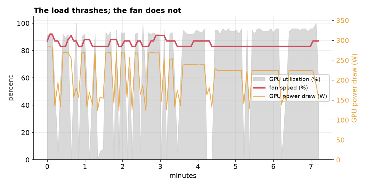
The steady-state trace under sustained heavy load answers the question I started with. Power shed down to the 225W floor and stayed there. Once settled, the fan sat at 83% (214 PWM, about 783 RPM) for 35 of the final 42 samples, stepping once to 87% on a load pulse, while raw GPU temperature ran 67-76°C underneath. The workload is doing whatever it wants. The fan barely moves.
Two honest caveats belong here. Convergence is deliberately slow, 15W every 20 seconds on the down-trim and 60 seconds on the up-trim, so under spiky load the fan can take a minute or two to settle, with brief excursions above budget before the average pulls back in line. And under the sustained full-load run above, the power floor of 225W was hit before the fan pulled all the way down to the 80% center, landing at 83%, inside the 75-85% band but not centered in it. Lowering PL_MIN further would pull that closer to 80% at the cost of more performance left on the table, a knob I haven’t turned yet.
Zooming out: after the tuning session the controller kept logging through an evening of unattended benchmark runs, about 1,600 samples at 4-second intervals spanning every power limit from 225 to 350W and draws from 10W idle to 347W.
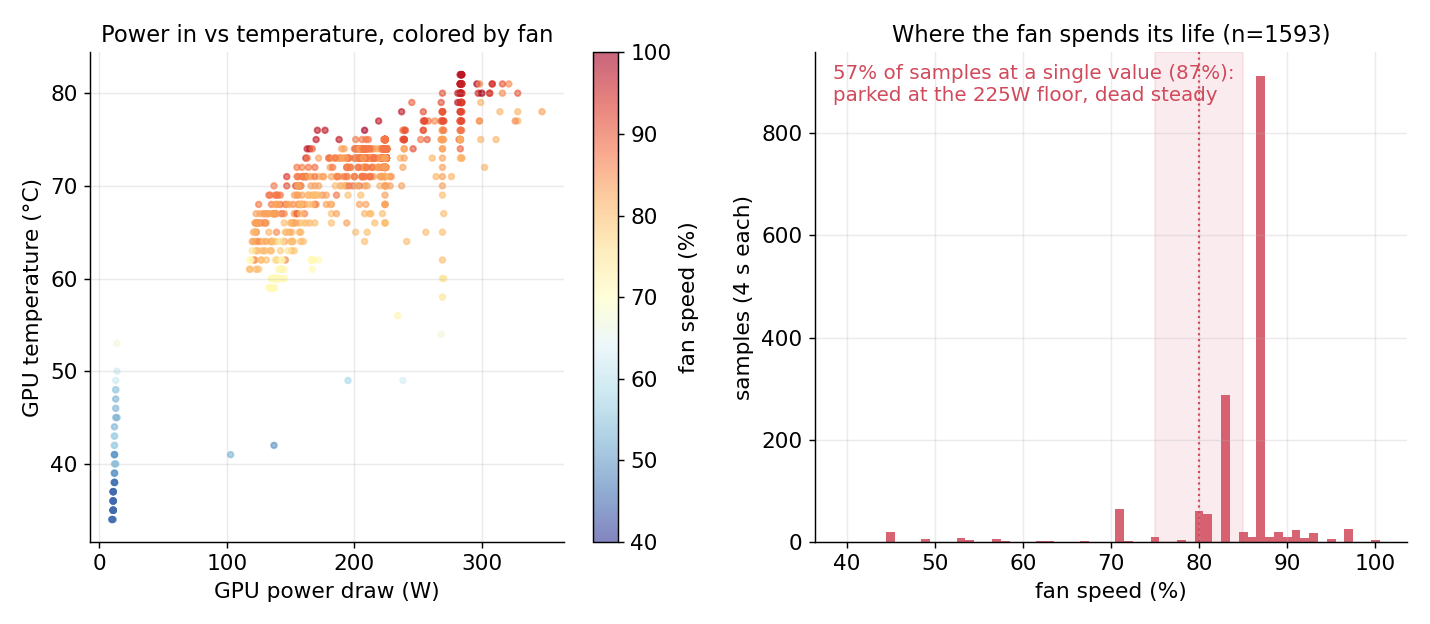 The full evening of recorded data: every operating point visited, and where the fan spent its time.
The left panel is the plant map: an idle column at 10W and 35-50°C with the fans at their floor, then the loaded cloud climbing from 120W to 347W with the color, fan speed, rising to meet it. The right panel is the steadiness claim as a distribution. The fan spent 57% of the entire log at exactly one value, 87%, parked there while the evening’s benchmarks hammered the card at the 225W floor: the longest stretch at the floor ran 926 consecutive samples with nine fan transitions. That 87% is one deadband step above the earlier run’s 83%: a warmer room and a heavier sustained load, with power already at its floor. When the governor has no authority left, the fan absorbs the difference by parking at a new steady level, and a level shift over hours is invisible in a way second-to-second hunting never is.
The fan holds still, the load doesn’t
The sign-flip, once more: Taylor drives his valve wide open because the valve costs nothing and the energy behind it does; here the fan is the cost itself, so the same reset sequence holds it at a cap instead of pushing it open.
What I’m left with is a controller that treats the fan the way a chilled-water plant treats its most demanding zone valve: as the signal that tells the slow variable how hard it’s allowed to work. The workload can spike from idle to 96% utilization and back a dozen times a minute, and from the couch three feet away it sounds like nothing changed at all.